Reading/writing eMMC
Some basic information
This repository contains some scripts, documentation how to upgrade the MIB2 firmware to a different SW/HW train (e.g.: 02xx → 03xx/04xx) and other things. The documentation is for the Technisat MIB STD2 unit without navigation and works also on units with navigation. It describes how to patch the swdownload binary, that the unit accepts updates for a higher HW train. Install the MIB2 Toolox, and other things (maybe soon).
Some of this informations are from another tutorial using Linux. I add the informations to use Windows and Qemu (nested Docs) and leave the additional Infos with Linux and modify the swdownload section for upgrade the SW as written before untouched as nested document. \n In addition to this (and nested) repository it's required to have access to theMIB Solutions. There you find the firmware updates and tools to patch the swdownload binary.
The tutorial will be continued.
Read/Write prepare the HW
Connect a SD card reader (SD Card Readers (working/not working)) to the eMMC through-hole plating (soldering or probes). For me the connection was only stable with DATA0 connected and DATA1-3 disconnected (slow read & write). You can bridge the VDD (3,3V) as seen on the second picture. The VDD is translated into two voltages values, one for the Core and the other for the I/O. Take into account that not all the eMMC chips use the same values for the Core Voltage (VCC) and the I/O Voltage (VCCQ), usually the VCCQ voltage is slightly lower. Also not all SD card readers give the full 3.3V. In the following pictures the VCC is at the top right and the VCCQ is at the bottom left. Usually VCC works with +2.7~+3.6V and VCCQ works with +1.1~3.6V, depending on the chip. There are some cases where VCCQ needs to be at least +2.1V and less than +2.4V; if the voltage exceeds that range the I/O part of the chip gets over-voltage protection and the dump is corrupted.
Working SD Card Readers
ZR
eMMC pinout (with all DATlines): \n 
-
Another pinout for ZR this box have emmc component on the bottom side of the card (Skoda 5Q0035819*):
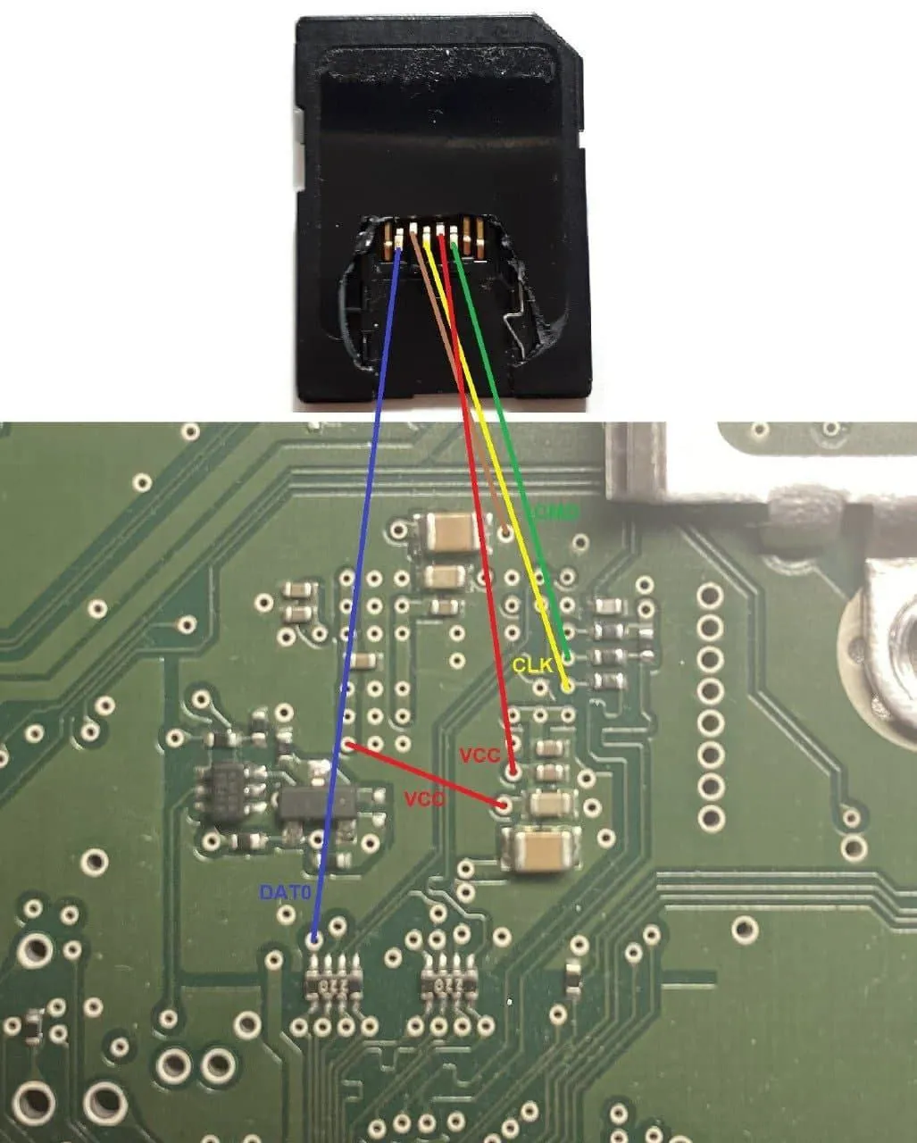
-
See this image for a SD card pinout (and
DAT0only) (theVCCtoVCCis a bridge from the upper left to the bottom left. If you dont want to use a bridge, you have to put the secondVCCto the bottom left).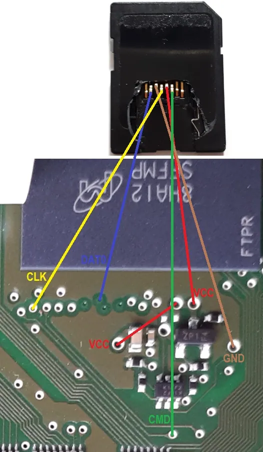
-
Voltage for
VCCQat +2.26V avoiding the I/O part of the chip to fail do to over-voltage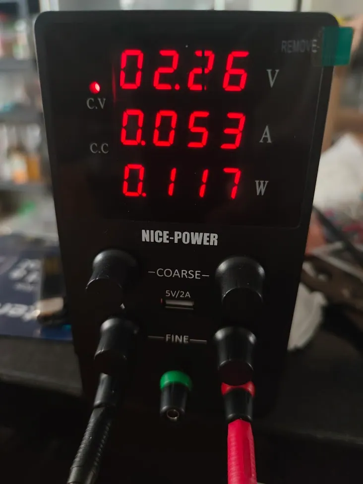
-
example of two different voltages for
VDD(VCCANDVCCQ) with alternative pinout (yellow isCMD, green isCLKand white isDAT0)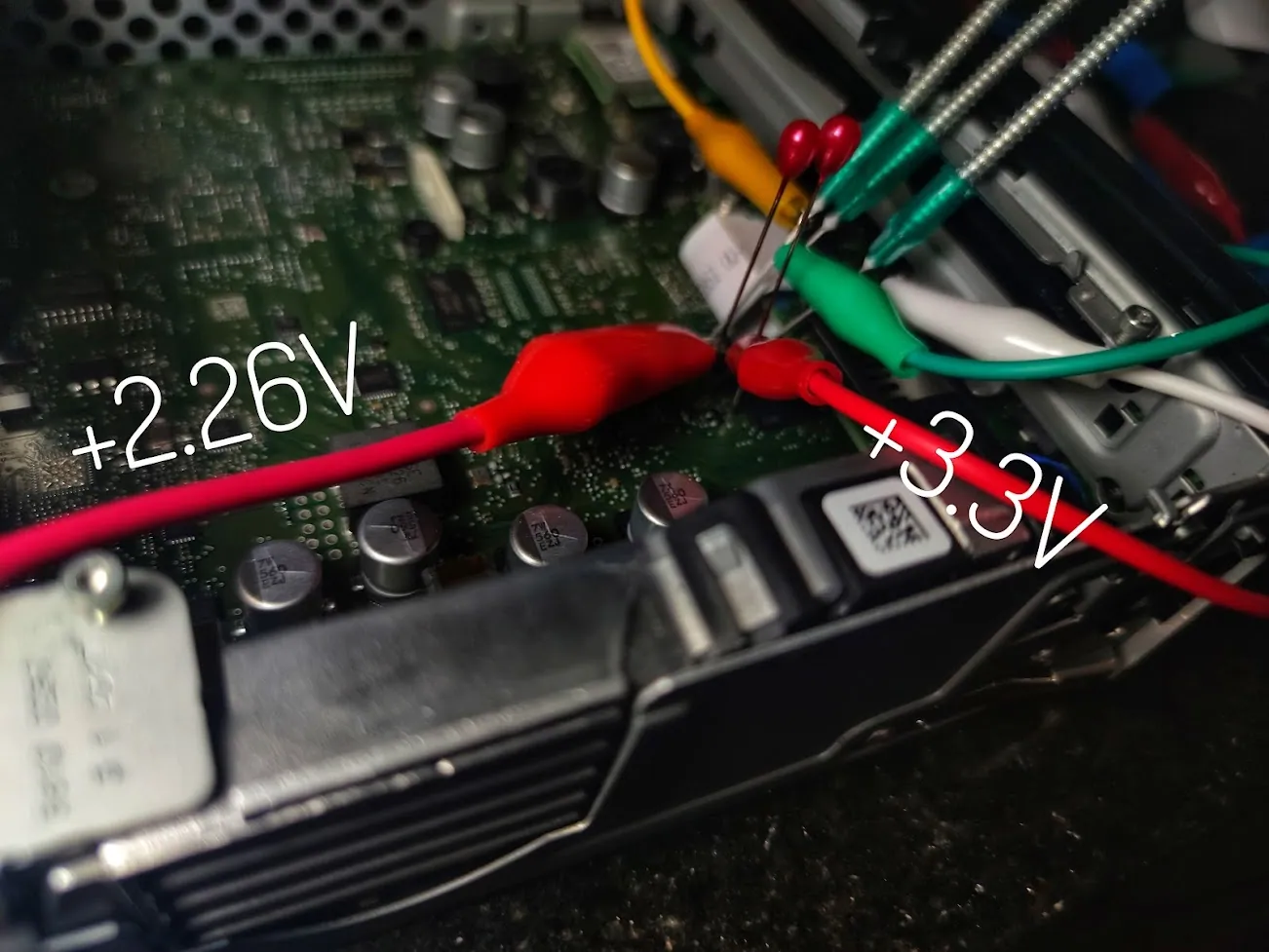
-
example ZR of probes soldered to a USB SD card reader (alternative pinout)

PQ
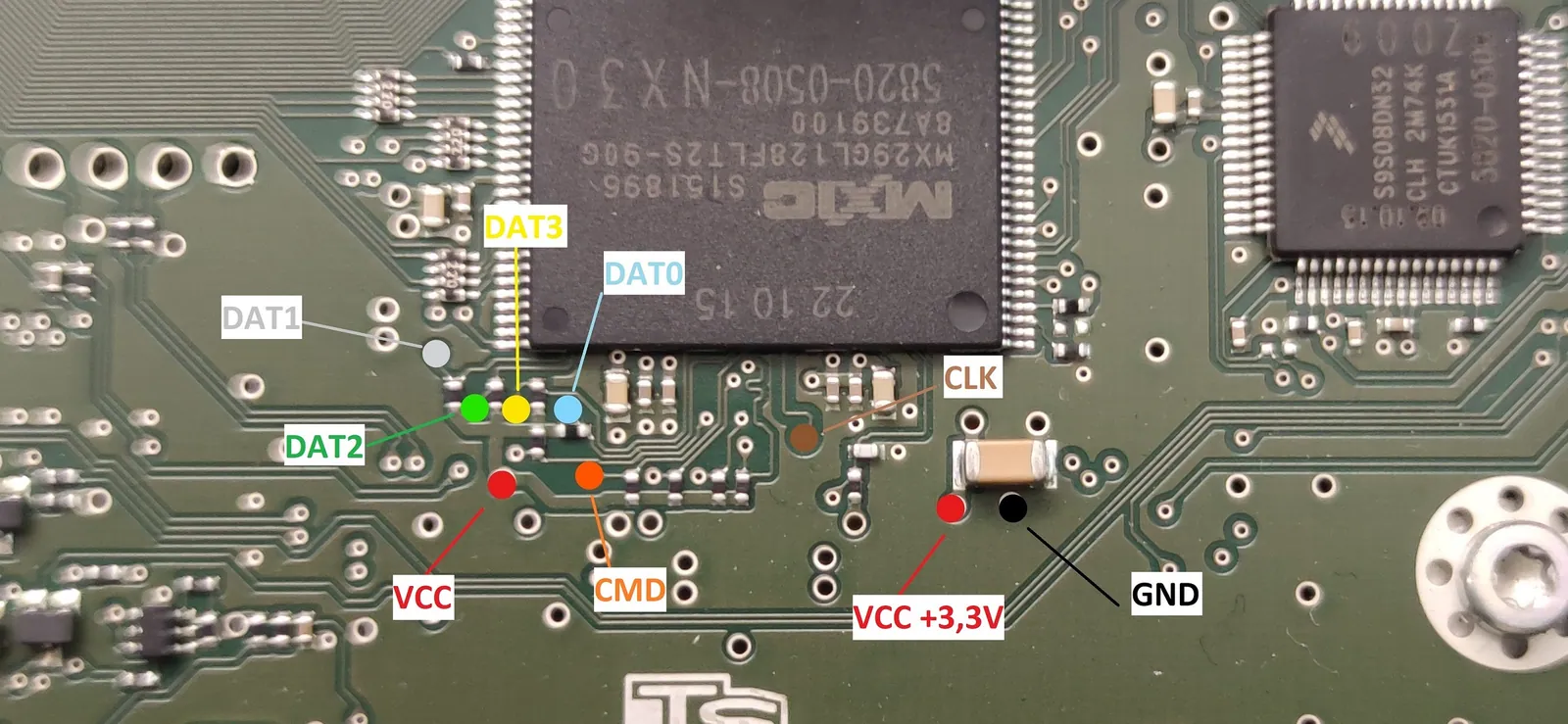
Windows 8/10
Read
Connect the wires/SD Card/Card Reader and open the HDD Raw Copy Tool
Select Source → Select your Card Reader (take a look at the nested Docs for working Card Readers)
Select Target → FILE save and name it where/as you want (Dump.img for example)
START. It will take some time because reading/writing with only one DAT0 line happens with around 5MB/s. (ZR Units)
Write
Connect the wires/SD Card/Card Reader and open the HDD Raw Copy Tool
Select Source → FILE (Dump.img - After you modified your data or want to write a backup)
Seldect Target → CardReader
START. It will take some time because reading/writing with only one DAT0 line happens with around 5MB/s. (ZR Units)
Linux
(the original mibwiki.one link is no longer available)
Useful References
- https://www.digital-eliteboard.com/threads/mib2-std-pq-zr-how-to-update.494459/
- https://forum.xda-developers.com/t/success-to-hack-technisat-mib2-infotainment-system.3584185/
- https://www.drive2.ru/l/573969809784439237/ (use google translator)
- https://www.drive2.ru/l/568827668779238365/ (use google translator)
Useful Adapter if you dont want to use a micro SD/SD Adapter and some other parts…
BDM probes
Glass fiber pen (if you want to clean the PCB from the green shell)
Solder resist ink (green) for fixing the cleaned parts
Community content mirrored from mibwiki.one. Always make a backup before flashing or coding a unit.